Analysis of the newly released FIU bridge plans has revealed that my earlier suspicion -
What we didn't know but now know because I have since calculated it - were the likely axial forces along member #11.
The compression force from the dead weight of the bridge I calculated as - 1367 kip.
The compression force from the P.T. bars - I calculated had to be at least 304 kip but in practice would have been more, perhaps significantly more so we should treat the P.T. bar force as a live load.
So the unfactored load on member #11 was at least 1367 + 304 = 1671 kip.
Factoring the load as 1.2 x DL + 1.6 x LL suggests they should have designed for a
Maximum allowable design factored load of 1367 x 1.2 + 304 x 1.6 = 2127 kip
I estimated from the NTSB video that member #11 used 10 x #7 bars which would suggest it was suitable for a factored load of only 2006 kip. which corresponds to a ratio of factored to unfactored load of 2006/1671 = 1.2.
that member 11 was dangerously under-reinforced has been
confirmed, to such a degree that the
collapse of member 11 under the compression load after the bridge was placed on the piers but before destressing was to be
expected.
The first point to note from the plans is that the plan's P.T. bar tensioning begins once the concrete reaches a strength of 6,000 psi or more, as this quote shows -
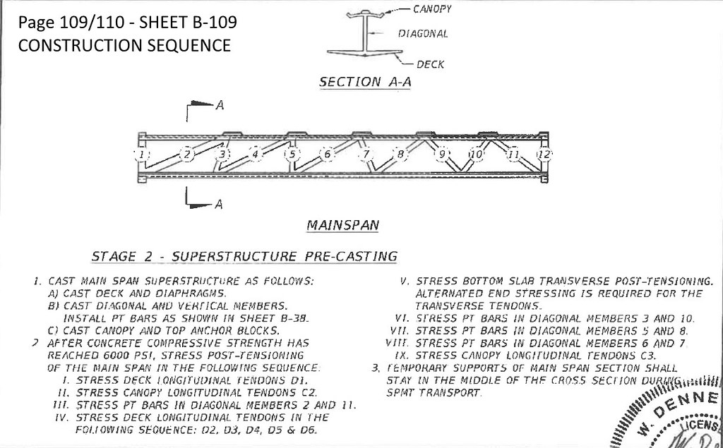
"CONSTRUCTION SEQUENCE - STAGE 2 - SUPERSTRUCTURE PRE-CASTING
2. AFTER CONCRETE COMPRESSIVE STRENGTH HAS REACHED 6000 PSI, STRESS POST-TENSIONING OF THE MAIN SPAN IN THE FOLLOWING SEQUENCE ..."
Next, I have shown in my post on Saturday -
Florida Department of TRANSPORTATION - Denney Pate signed and sealed FIU bridge construction plans - 2016 & 2017
https://cdn2.fdot.gov/fiu/13-Denney-Pate-signed-and-sealed-FIU-bridge-construction-plans.pdf
From this new information ...
- which is completely different from the PT bar tensioning requirements suggested in the proposal pdf, but there still doesn't seem to be any obvious method employed in calculating the PT bar tension from the maximum tension force in the truss members that I calculated.
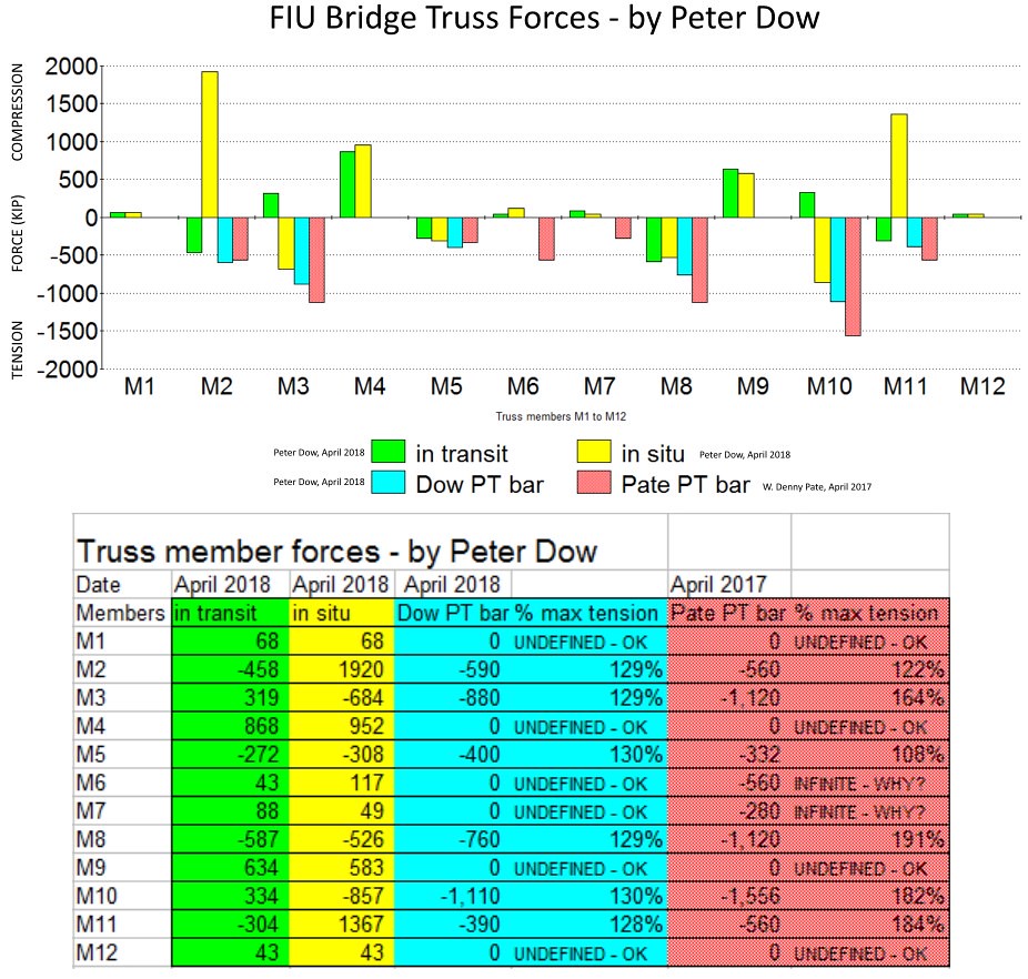
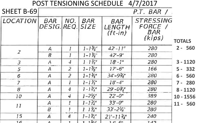
- that the plans recommend a P.T. bar setting for the 2 P.T. bars in member 11 which together total a P.T. bar tension of 560 KIP.
Together with the results of my truss calculations, also reported again in my post of Saturday, the dead weight of the bridge exerts a tensile force of 304 KIP while the bridge is being transported and a compressive force of 1367 KIP when the bridge is placed on the piers.
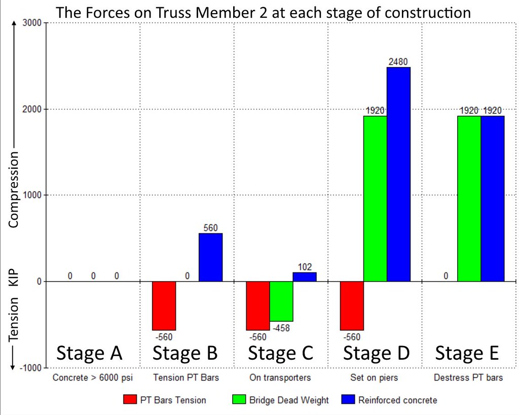
Now let us consider what all those forces together in the sequence they were applied mean for the compressive force on the reinforced concrete of member 11.
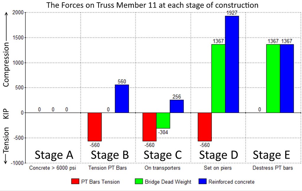
I have considered 5 different stages, A, B, C, D and E. The bridge collapsed either in stage D or as a result of damage sustained in stage D, so the bridge never got to stage E in good order, sadly, but inevitably given the plan followed.
Stage A
The concrete has hardened to at least 6,000 PSI and so post tensioning is about to begin but at this stage the mainspan is still resting on the ground, so there are no troublesome forces on member 11, no PT bar tension, no bridge dead weight and so the reinforced concrete is not being compressed very much at all except under its own weight and that of the canopy immediately above it, but we will ignore that for now.
Stage B
The P.T. bars of member 11 have been tensioned to the recommended amount - a total of 560 KIP and that tension force on the P.T. bars is being provided by an equal and opposite compressive force of 560 KIP on the reinforced concrete. But the mainspan is still on the ground so not much in the way of dead weight of the bridge to worry about yet.
Stage C.
The mainspan has been lifted onto the transporters and now the dead weight of the bridge is exerting an external tension force of 304 KIP on member 11. This has the effect of reducing the compressive force on the reinforced concrete of member 11 by 304 KIP down to 256 KIP.
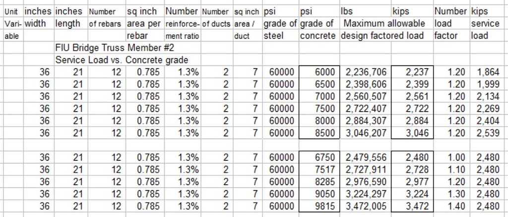
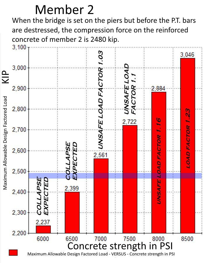
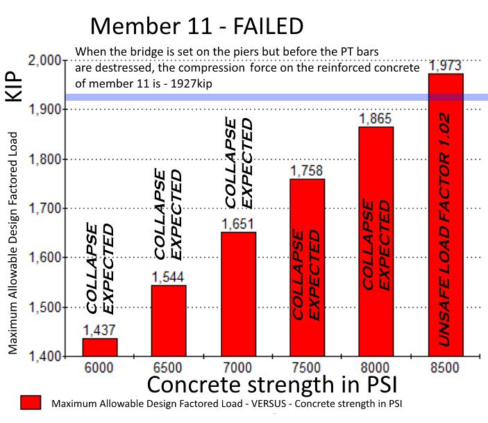
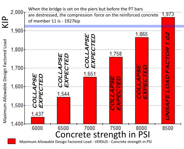
Stage D, "D" for danger and for "Doom". This is when things take a turn for the worse. The bridge gets placed on the piers and now the dead weight of the bridge is applying a compressive force of 1367 KIP on to member 11. So now the reinforced concrete has to take the full 560 KIP from the P.T. bars plus the 1367 KIP dead weight to suffer a whopping 1927 KIP of compressive force, which is more than the member is able to cope with, especially so if the concrete has not reached is full strength of at least 8500 PSI, as is shown in this table from my concrete column calculator and this bar chart.
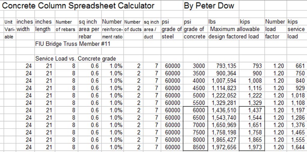
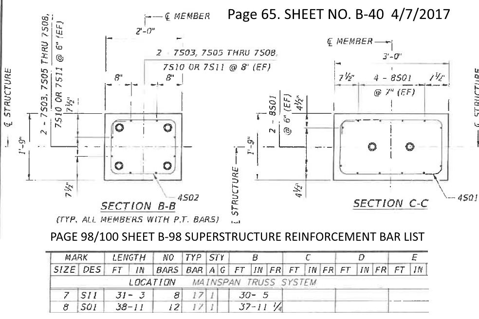
The plans only call for 8 number 7 (diameter 7/8" inch, area 0.6 square inches each, axially orientated reinforcing bars, just barely 1% of a reinforcement ratio for that size of concrete member.
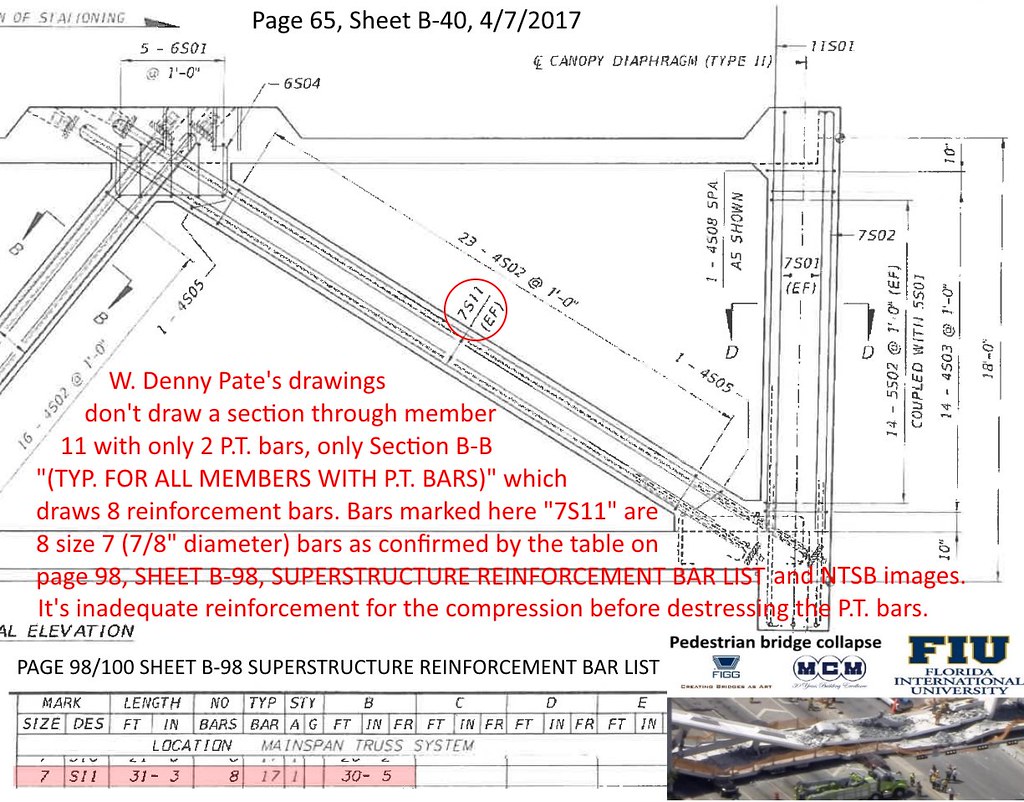
As I have noted there, W Denney Pate's drawings don't draw a section through member 11 with only 2 P.T. bars, only section B-B "(TYP. FOR ALL MEMBERS WITH P.T. BARS)" which draws 8 reinforcement bars. Bars marked here "7S11" are 8 size 7 (7/8" diameter) bars confirmed by the table on page 98, SHEET B-98, SUPERSTRUCTURE REINFORCEMENT BAR LIST AND NTSB images.
It's inadequate reinforcement for the compression before destressing the P.T. bars.
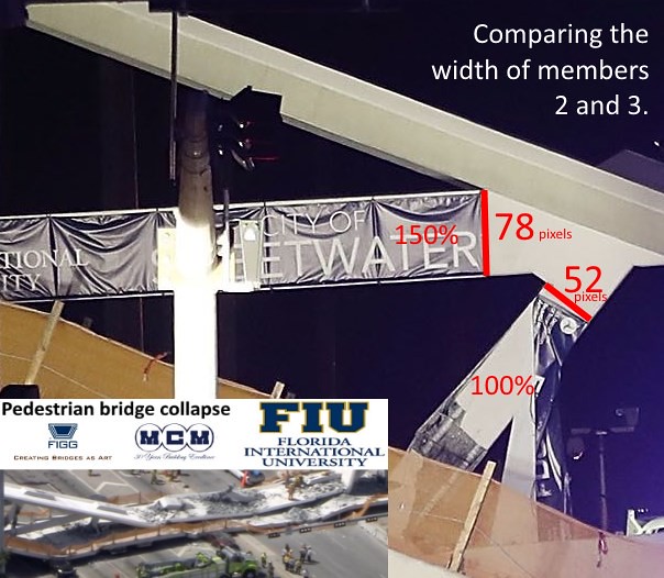
So it turns out that this picture was "the smoking gun" after all, but not for the reason I thought at the time, but because it shows one of the far too small and far too few reinforcement bars, marked "<-B->".

Stage E. After destressing is complete. We don't know for sure if this stage was actually reached, but even if it was, by that time the damage was done and the member 11 was failing and bridge had begun the process of collapsing and it was just a matter of time.
One small post for a scientist, one giant leap for forensic engineering.
")